
CircuitPython LTC166X DAC - control of daisy-chained DACs
I’ve been working on CircuitPython library for control of the Linear Technology LTC166X 8 channel DACs for new instrument project. I decided to follow the full Adafruit guide on Creating and Sharing a CircuitPython Library to make it available to the community. As part of the documentation I wanted to provide a tutorial for one of the more complex use cases of the LTC166X series DACs, serial interface daisy-chaining.
Hardware
A CircuitPython compatible microcontroller. I’m using a Pimoroni Tiny 2040 in this tutorial.
2 or more LTC166X DACs. I’ll be using the LTC1665CN 8 bit 8 channel DAC.
A breadboard and jumper wires.
A way to view the analog output of the DAC. I’ll be using an oscilloscope made from an Arduino UNO.
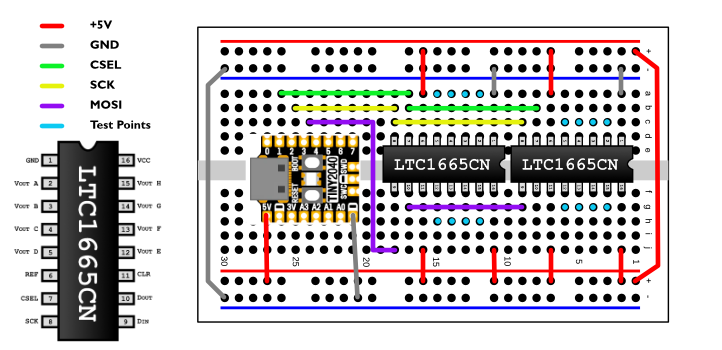
DAC Chain breadboard layout.
Follow the diagram above or adjust as needed based on your microcontroller. The important connections are for SPI serial; CS, SCK, and MOSI. All DACs in the chain will share the CS and SCK. The first DAC in the chain will receive the MOSI on its DIN. The first DAC DOUT will connect to the next DAC DIN and so on down the daisy-chain.
Note: This library uses CSEL in place of CS or CS/LD for pylint variable naming conformity.Software
Install CircuitPython
Install the LTC166X library
See the code example below, which is also provided as an example with the library. It takes a list of lists to represent the values of each DAC’s channels. Feel free to load this code and test it with your setup. Don’t forget to change the csel, sck, and mosi values if you are using a different microcontroller.
# SPDX-FileCopyrightText: 2017 Scott Shawcroft, written for Adafruit Industries
# SPDX-FileCopyrightText: Copyright (c) 2023 Thadeus Frazier-Reed for creativecontrol
#
# SPDX-License-Identifier: Unlicense

"""
Example of using a DAC daisy-chain as described in the LTC166X datasheet
https://www.analog.com/media/en/technical-documentation/data-sheets/166560fa.pdf
"""

import time
import board
import creativecontrol_circuitpython_ltc166x

ltc1665 = creativecontrol_circuitpython_ltc166x.LTC1665(
    csel=board.GP1, sck=board.GP2, mosi=board.GP3, debug=True
)

dac_values = [
    [1, 3, 7, 15, 31, 63, 127, 255],
    [255, 127, 63, 31, 15, 7, 3, 1]
]

while True:
    print("writing dac values ", time.monotonic())
    ltc1665.write_chained_dac_values(dac_values)
    time.sleep(4)
    print("off")
    ltc1665.write_chained_dac_values([[0] * 8, [0] * 8])
    time.sleep(4)
How does daisy-chaining work?
The LTC166X datasheet describes the daisy-chaining process like this.
Multiple LTC1665/LTC1660’s can be controlled from a single 3-wire serial port (i.e., SCK, DIN and CS/LD) by using the included “daisy-chain” facility. A series of m chips is configured by connecting each DOUT (except the last) to DIN of the next chip, forming a single 16m-bit shift register. The SCK and CS/LD signals are common to all chips in the chain. In use, CS/LD is held low while m 16-bit words are clocked to DIN of the first chip; CS/LD is then pulled high, updating all of them simultaneously.
I felt this description didn’t quite explain exactly how this process works. So let’s look at how values are sent from the microcontroller to the LTC166X.
If we want to send a single value to a single DAC we do the following:
open SPI, send value to DAC address, release SPIIf we want to send values to two different channels on a single DAC we would:
open SPI, send value 1 to DAC address A, release SPI, open SPI, send value 2 to DAC address B, release SPIBecause the DAC has a single 16 bit register, it can only hold one value at a time so we release the SPI (pull csel high) to load the value to the DAC channel before sending the next value to the register. This register can also be used to load all channels with the same value by using the address 1111.
Everything works slightly differently with the daisy-chain because each DAC in the chain has its own 16 bit register. As the registers fill up they are shifted to the next DAC in the chain.
open SPI, send value 1 for last DAC in chain, send value 2 for first DAC in chain, release SPIThe detail that was not clear to me from the datasheet was that the value was shifted as it was loaded rather than filling up the first in the chain, then the second, and so on. I was probably assuming this functioned like addressable LEDs rather than really understanding shift registers.
This means we must reverse our list of numbers so the first number gets shifted to the end of the chain and the first DAC in the chain is filled last; like pushing them down a pipe rather than stacking them on top of each other. The values are then all applied when the SPI is released / CSEL is pulled high.

DAC daisy-chain register shift.
The daisy-chain method
def write_chained_dac_values(self, dac_values: list):
    for dac_index, _ in enumerate(dac_values[0]):
          dac_chain_list = [dac[dac_index] for dac in dac_values]
          # DAC chain is reversed because of the way the shift register works.
          dac_chain_list.reverse()
          with self._device as spi:
            for chain_value in dac_chain_list:
                if chain_value >= 0:
                    self.write_value_to_spi(spi, chain_value, dac_index + 1)
                else:
                    self.write_value_to_spi(spi, 0, 0)
We can see in the method above how the library deals with this.
create a list of values for channel A for all DACs
reverse the list
open the SPI
write each value in the list we have created
if you have marked a value for no change using a -1, write a no change placeholder
release the SPI
repeat for each channel
Testing
To test that the DAC output is working you can use any oscilloscope you may have. If, like me, you don’t happen to have one, you can use this simple 4 channel Arduino Scope I put together by modifying a couple other projects. Just download from my GitHub and follow the instructions in the README.

Testing setup
Below we can see the output from the Arduino Scope 2 for DAC channels A through D on the second DAC in a daisy-chain.
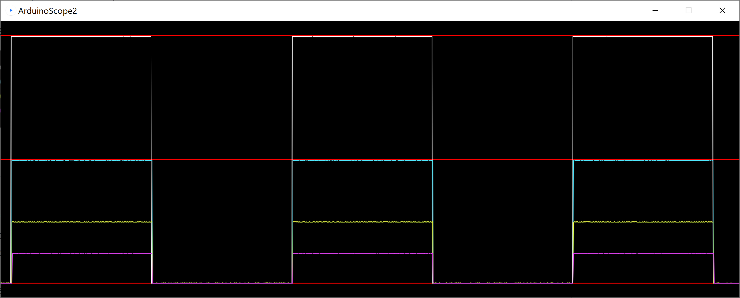
Arduino Scope 2 output.
If you’ve read this far I hope these explanations and tools have proved useful. Enjoy !